PID Temperature Controller
ITC-100
User Manual
Version 2.0s
Inkbird Tech. Co., Ltd.
Copyright
Copyright
©
2016 Inkbird Tech. Co., Ltd. All rights reserved. No part of this document may be reproduced
without prior written permission.
Disclaimer
Inkbird has made every effort to ensure that the information contained in this document is accurate and
complete; however, the contents of this document are subject to revision without notice. Please contact
Inkbird to ensure you have the latest version of this document.

IHC-200 User Manual
Inkbird Tech. Co., Ltd. www.ink-bird.com
2
Contents
1. Safety Precautions …………………………………………………………………………………… 3
2. Specification ………………………………………………………………………………………….. 3
Mounting dimension …………………………………………………………………………………………………. 3
Main Features …………………………………………………………………………………………………………. 3
3. Connection ……………………………………………………………………………………………. 5
3.1 Dimension …………………………………………………………………………………………………………. 5
3.2 Connection ………………………………………………………………………………………………………… 5
4. Front Panel and Operation …………………………………………………………………………. 5
5. Operation Process ……………………………………………………………………………………. 6
5.1 Input Type ………………………………………………………………………………………………………… 6
5.2 Alarm Function Setting …………………………………………………………………………………………. 7
5.3 Error Display (Fault Diagnosis) ……………………………………………………………………………….. 7
6. Operating instruction ……………………………………………………………………………….. 7
7. Parameter Setting and Defining …………………………………………………………………… 8
User-defined Parameter …………………………………………………………………………………………….. 9
Datalock (LOC) ………………………………………………………………………………………………………… 9
8. Technical Assistance and Warranty …………………………………………………………….. 10
8.1 Technical Assistance ………………………………………………………………………………………….. 10
8.2 Warranty …………………………………………………………………………………………………………. 10

IHC-200 User Manual
Inkbird Tech. Co., Ltd. www.ink-bird.com
3
1. Safety Precautions
Ensure the product using within the specification.
Do not touch the terminals at least while power is being supplied. Doing so may
occasionally result in injury due to electric shock.
Do not allow pieces of metal, wire clippings, or fine metallic shaving or filings from
installation to enter the product. Doing so may occasionally result in electric shock,
fire, or malfunction.
Do not use the product where subject to flammable or explosive gas. Otherwise,
injury from explosion may occasionally occur.
Never disassemble, modify or repair the product or touch any of the internal parts.
Electric Shock, fire, or malfunction may occasionally occur.
If the output relays are used past their life expectancy, contact fusing or burning may
occasionally occur. Always consider the application conditions and use the output
relays within their rated load and electrical life expectancy. The life expectancy of
output relays varies considerably with the output load and switch conditions.
2. Specification
Mounting dimension
Front Panel Dimension: DIN (48WmmX48Lmm)
Cutout size: 45x45mm
Main Features
Support Multiple Thermocouples and Resistance Sensors (K, S, Wre, T, E, J, B, N,
CU50, PT100)
Wide Controlling Range: –50~1300ºC (K sensor)
High Accuracy of Displaying and Controlling 0.1ºC, Accuracy of Measurement
±0.2%FS
PID and ON/OFF Control Mode, High Standard Self-adjusting Function
Multiple Outputs and Alarm Modes
Build-in Adjustable Digital Filter Reduce Interference
The Self-adjusting Function and Intelligent Control of the Instrument Ensure the Long-
term Stability
High Luminance, 0.39” height LED display, Anti-glare panel
Built-in Switch Power Supply, Wide Voltage Range and Low-power Consumption
IHC-200 User Manual
Inkbird Tech. Co., Ltd. www.ink-bird.com
4
Units
Degree Celsius (<1000ºC)
Weight
Approx. 140g
Power Supply Voltage
AC 100-240V ±10% 50/60Hz
AC/DC 12-24V ±10% 50/60Hz
DC 12-24V ±10%
Operating voltage range
85~110% Rated voltage
Power Consumption
Approx. 5VA(100~240VAC)
Approx. 4VA(12~24VAC)
Approx. 3W(12~24VDC)
Display Character
PV: 4 digital 9.9mm height Red LED Letters
SV: 4 digital 8mm height Green LED Letters
Display Accuracy
±0.2%FS 0.1ºC(<1000ºC);1ºC(≥1000ºC)
Period of Sampling
0.5S
Temperature Compensation
0-50ºC
Main Output
Relay Contact Output (ITC-100R):
AC250V 3A (Resistive load) ON/NC.
Alarm 1 AC250V 3A (Resistive load) ON/NC.
Voltage Pulses Output (ITC-100V):
DC 12V, 30mA;
Alarm 1 AC250V 3A (Resistive load) ON/NC
Life Expectancy of Relay
Mechanical≥10,000,000 operations
Electrical≥10,000,000 operations
Storage Temperature
–25~65ºC(no icy or condensation)
Data Storage
10year
Mounting Method
Flush mounting and screw terminals
Environmental Conditions
–10~55ºC(no icy or condensation), RH 35-85% Humidity
IHC-200 User Manual
Inkbird Tech. Co., Ltd. www.ink-bird.com
5
3. Connection
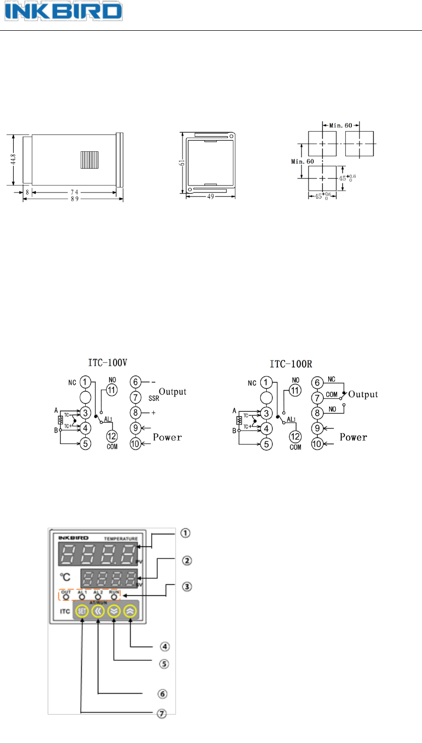
3.1 Dimension (unit: mm)
Shell Mounting bracket Panel Cutout
Push the instrument into the hole of panel and insert mounting bracket from back side,
ensure that there are no gaps between the panel and mounting bracket, and then
screw cap down.
Ensure that the ambient temperature should not be exceed the specified working
temperature, especially when installed more than two instruments.
3.2 Connection
4. Front Panel and Operation

IHC-200 User Manual
Inkbird Tech. Co., Ltd. www.ink-bird.com
6
① PV: Process Value
Measured Value/Mode Value
② SV: Setting Value.
Set Value/ Mode Context Value
③ Status Display LED
OUT:Output pilot lamp
AL1:Alarm1 pilot lamp
AL2:Alarm2 pilot lamp
RUN:Manual pilot lamp
④ Up Key: Increase the value in setting, Keep pressing can increase value quick.
⑤ Down Key: Decrease the value in setting, Keep pressing can increase value quick.
⑥ Move Key: When setting temperature value or parameter, press “《 “ Key to switch to
the value needed
Self-Adjustment Key: When SV/PV at normal display, keep pressing the “《 “ Key
more than 2S to start or end self-adjusting function.
Shift Key: When SV/PV at normal display, press “《 “ Key less than 1S to shift between
automatic and manual control modes.
⑦ SET Key: When SV/PV at normal display, press the SET key to check PV and SV value, keep
pressing it more than 2 seconds can access parameter setting mode.
5. Operation Process
5.1 Input Type (Table1)
Input Type
Input
Value
Measuring Range
Thermocouple
K
0
–50~1300ºC
S
1
–50~1700ºC
Wr
2
-0~2300ºC
T
3
–2000~350ºC
E
4
0~1000ºC
J
5
0~1000ºC
B
6
0~1800ºC
N
7
0~1300ºC
Cu resistance
CU50
20
–50~150ºC
Platinum
resistance
PT100
21
–200~600ºC
IHC-200 User Manual
Inkbird Tech. Co., Ltd. www.ink-bird.com
7
5.2 Alarm Function Setting(Table 2)
Alarm Output
Alarm Type
ALP Value
AL1 Output
Upper Alarm Limit
0
Lower Alarm Limit
0
Maximum Deviation Alarm
0
Minimum Deviation Alarm
0
AL2 Output
Upper Alarm Limit
1
Lower Alarm Limit
2
Maximum Deviation Alarm
4
Minimum Deviation Alarm
8
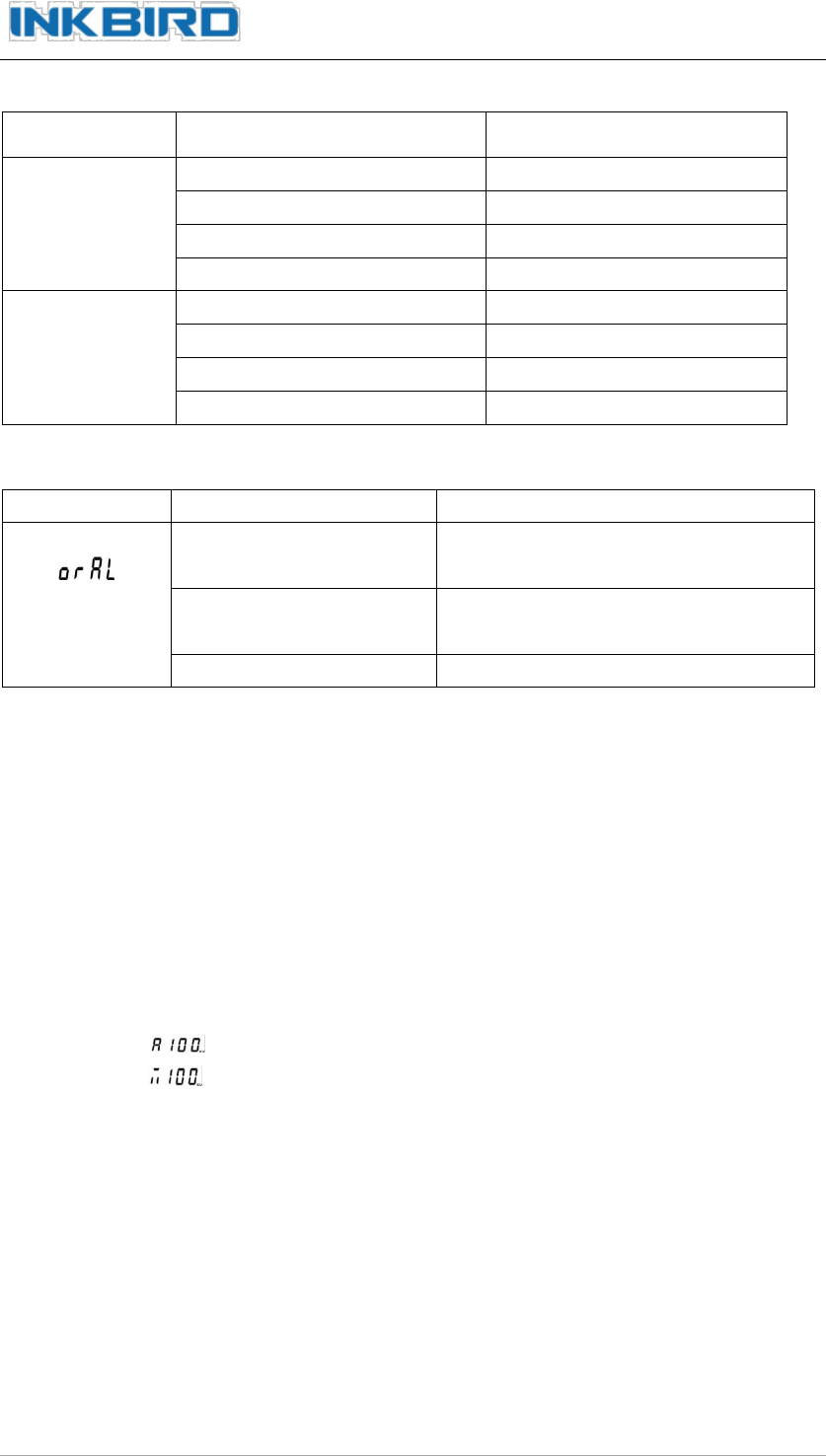
5.3 Error Display (Fault Diagnosis)
SV Display
Explain
Remedy
Input Sensor Selected
Error
Input the correct value consistent with
parameters of sensor
(orAL)
Signal Wire Connected
Error
Correct the Connecting Signal Wire
Sensor Fault
Check the sensor
6. Operating instruction
After power-on, PV screen displays current measured value and SV screen displays
current set value, the instrument is in this normalstatus. If PV/SV screen displays
“orAL” alternately, it means that input value is out of range (or sensor is open circuit)
or input setting is incorrect. When there is alarm output, SV screen displays character
related with alarms: HiAL (Upper Alarm Limit), LoAL (Lower Alarm Limit),
dHAL(Maximum Deviation Alarm), dLAL (Minimum Deviation Alarm).
Checking Output Value: Press “SET” Key (no more than 1S), If SV screen displays
“A”,( e.g.: ), the status is automatic control output; If SV demo display
“M”,( e.g.: ), the status is manual control output.
Auto/Manual Switch: Press “《“Key (no more than 1S),can switch the instrument
between automatic control and manual control status. In automatic control status,
RUN pilot lamp is off; in manual control status, RUN pilot lamp is on. (Remarks: If
status of setting function is “2: No manual”, it cannot operate like this.)
Temperature Setting: When SV screen displays setting value, press “︽”key(or“︾”
key)can increase( or decrease) setting value. Press“《”key can move the place of
update data. If keep pressing “︽”Key (or“︾”Key), can set the value quick.
Start the Self-adjusting Function: At the first-time use, please use self-adjusting
function to determine the control parameters (M50, P and T parameter), so it can
obtain ideal controlling. Keep pressing the “《”key for more than 2S, SV screen
IHC-200 User Manual
Inkbird Tech. Co., Ltd. www.ink-bird.com
8
displays “AT” alternately (Character: ), the instrument is in self-adjusting status. In
this status, the instrument will execute position adjustment by 2 – 5 times oscillations,
then it will turn out PID control parameter automatically (M50, P and T parameter).
The instrument will return to PID automatic control status at the end of self-
adjustment. If user want to quit in the course of self-adjusting, keep pressing “《”
key for more than 2S, till “AT” character in the SV screen disappears.
Attention: If user wants to use self-adjusting function again after first using, user
needs to set “CtrL” to be “2” to start it (more information please check “Parameter
Setting and Defining”). The parameter values of adjusting control are not the same at
the different setting temperatures, so please execute self-adjustment at the most
common setting value of the system. If the setting values change often, user can
modulate with the median.
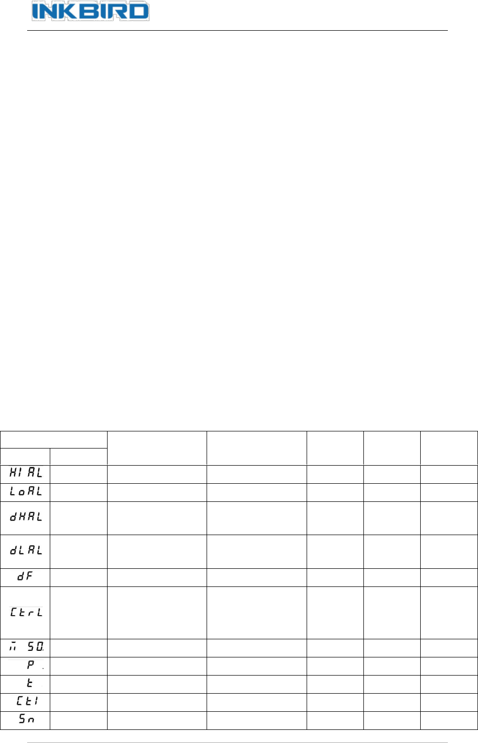
7. Parameter Setting and Defining
After power-on, keep pressing the “SET” key for more than 2S to enter setting mode. User
can use “︽”Key(or“︾”Key)to set the value. After finishing, press “SET” keyto confirm
and enter next function setting. PV/SV screen will be in normal display after setting.
Note: If there are modified operations in setting mode, the instrument will save current
value automatically after no operation for more than 10 seconds, and return to normal
status.
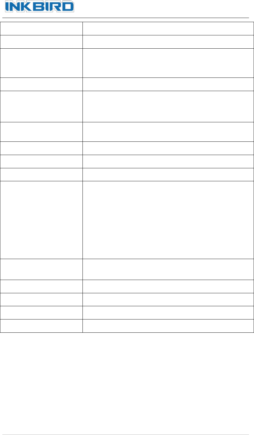
Function Setting
Description
Setting Range
Unit
Remarks
Factory
Default
Code
Name
HIAL
Upper Alarm Limit
–1999~+9999
1℃
9999
LoAL
Lower Alarm Limit
–1999~+9999
1℃
–1999
dHAL
Maximum
Deviation Alarm
0~9999
1℃
9999
dLAL
Minimum Deviation
Alarm
0~9999
1℃
9999
dF
Hysteresis
0~200.0
0.1℃
0.3
CtrL
Control Output
0:ON/OFF
3
1/3:PID
2: Self-adjustment
M50
Integral
0~9999
0.1℃
0: Cancel
1000
P
Differential
0~9999
0.01S/℃
500
t
Hysteresis Time
1~9999
S
120
Ctl
Control Period
1~120
S
4
Sn
Input Sensor
0~42
Table 1
0
IHC-200 User Manual
Inkbird Tech. Co., Ltd. www.ink-bird.com
9
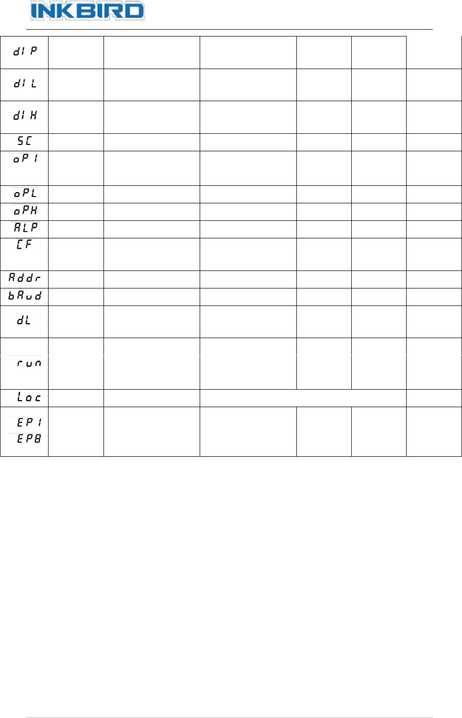
diP
Decimal Point
Position
0~3
1
diL
Input Lower Limit
Value
–1999~+9999
1 Digital
0
diH
Input Upper Limit
Value
–1999~+9999
1 Digital
1000
SC
Sensor Calibration
–199~+999
0
oP1
Output Mode
0/2:Time Duty
0
1:0-10mA
Opl
Output Lower Limit
0~220
1%
0
Oph
Output Upper Limit
0~220
1%
100
ALP
Alarm Function
0~31
Table 2
0
CF
System Function
2: Heater
2
3:Cooler
Addr
Address
0~63
1
Baud
Baud Rate
0~4800
9600
dl
Input Digital Filter
0~20
Filter
Effect
0
run
Run Mode
0:Manual
2
1:Automatoc
2:No Manual
LOC
Lock Function
0~999
40
EP1 ~EP8
8 User-defined
Parameters
Select any
Parameter from
this Table
Except
LOC and
EP1~EP8
none
User-defined Parameter: In the process of setting parameters, the display modes of
last eight parameters are difference from the previous. PV screen displays prompt EP1 –
EP8, SV screen displays various prompts of technical parameters Setting (e.g. HiAL, LoAL,
dHAL and so on). Press “︽”Key(or“︾”Key), The technical parameters in SV screen will
be listed in proper order as the above parameters table. After that, press “SET” key
confirm and enter next setting. “none” needs to be set if user don’t need to use the user–
defined parameter. Press “SET” key to set these 8 user-defined parameters till all to be set,
and then return to normal status.
Datalock (LOC): When the setting values of LOC are not “2”, “40” or “808”, the
instrument only allows to set 0-8 self-defined parameters and LOC parameters themselves.
User can set all parameters only when setting LOC value is “2”, “40” or “808”. Details are
as follows:
Loc=0, Temperature setting value and EP1-EP8 can be revamped.
Loc=1, Data can not be revamped, only can be checked.(Except LOC parameters)

IHC-200 User Manual
Inkbird Tech. Co., Ltd. www.ink-bird.com
10
Loc=2,40,808,all of parameters can be revamped.
8. Technical Assistance and Warranty
8.1 Technical Assistance
If you have any problems installing or using this thermostat, please carefully and
thoroughly review the instruction manual. If you require assistance, please write us to
[email protected]. We will reply your emails in 24 hours from Monday through Saturday.
You can also visit our web site www.ink-bird.com to find the answers of the common
technical questions.
8.2 Warranty
INKBIRD TECH. C.L. warrants this thermostat for one years from the date of purchase
when operated under normal condition by the original purchaser (not transferable), against
defects caused by INKBIRD’s workmanship or materials. This warranty is limited to the
repair or replacement, at INKBIRD’s discretion, of all or part of the thermostat. The
original receipt is required for warranty purposes.
INKBIRD is not responsible for injury property damage or other consequential damages or
damages of third parties arising directly from an actual or alleged in mater of workmanship
of the product.
There are no representations, warranties, or conditions, express or implied, statutory or
otherwise, other than herein contained in the sale of goods act or any other statue.
Contact Us
Business Contact: [email protected]
Technical Support: cs@ink-bird.com
Business Hours: 09:00-18:00(GMT+8) from Monday to Friday
URL: www.ink-bird.com